Newsletter Subscribe
Enter your email address below and subscribe to our newsletter

 ByJohn A
Industrial electrical networks depend on reliable power distribution, effective fault protection, and carefully engineered grounding arrangements. In facilities that use delta-connected transformers, grounding requires particular attention because a delta winding does not provide an accessible neutral point in the same way as a grounded star-connected winding. This can influence how the network responds to earth faults, how protective devices operate, and how electrical equipment is protected.
Evaluating grounding delta transformer requirements involves more than selecting a transformer with the correct voltage and power rating. Engineers must consider the network configuration, grounding method, fault-current limits, protection coordination, and applicable electrical standards. A properly designed arrangement helps industrial facilities balance personnel safety, equipment protection, and operational continuity.
The importance of sound electrical system planning when evaluating transformer grounding requirements for industrial applications. Understanding the technical factors behind grounding decisions helps facility managers, electrical engineers, and project planners make better-informed choices for new installations and existing network upgrades.
A delta-connected transformer uses three windings connected in a closed loop. This configuration is widely used in three-phase electrical systems serving industrial motors, manufacturing equipment, pumps, and other heavy-duty loads.
One important characteristic of a conventional delta winding is that it does not provide a neutral terminal. Consequently, the grounding arrangement cannot always follow the same approach used for a grounded wye-connected system.
Depending on the design, a delta system may operate ungrounded, use corner grounding, or incorporate a grounding transformer to establish an appropriate system grounding point. Each option has different implications for earth-fault detection, insulation stress, and protection requirements.
Engineers should therefore assess the actual transformer connections and the intended operating characteristics before selecting a grounding method.
Grounding provides a defined relationship between the electrical system and earth, helping control system voltages during abnormal conditions and supporting the operation of protective devices.
In industrial environments, an unsuitable grounding arrangement can create several problems:
The consequences depend on the system configuration and fault conditions. Grounding must therefore be evaluated as part of the complete electrical protection design rather than as an isolated transformer specification.
The first step is to establish how the industrial network is configured. Engineers should review the transformer nameplate, winding connections, rated voltage, available fault current, connected loads, and existing grounding equipment.
The assessment should also identify whether the system is supplied by a single transformer, several parallel sources, generators, or alternative power sources. These arrangements can affect grounding continuity and fault-current paths.
For an existing installation, engineers should examine available single-line diagrams and protection settings, then verify that the documented configuration matches the equipment in service.
This initial review helps determine whether the current grounding method remains suitable for the facility’s electrical demand and operating conditions.
The choice of grounding method depends on the application, operating voltage, equipment requirements, and the consequences of an earth fault.
An ungrounded delta system has no intentional connection between its phase conductors and earth. A first ground fault may produce relatively low current, depending on the network’s distributed capacitance and other electrical characteristics.
Although this arrangement can allow continued operation under certain conditions, it does not eliminate risk. A second ground fault on another phase can create a severe phase-to-phase fault through the grounding paths. Ground-fault detection and insulation monitoring are therefore important considerations.
In a corner-grounded delta arrangement, one phase conductor is intentionally connected to earth. This establishes a system reference without creating a conventional neutral point.
The approach may suit specific existing installations, but it affects phase-to-earth voltages and equipment selection. Switchgear, overcurrent devices, monitoring equipment, and connected loads must be suitable for the resulting configuration.
Engineers should also confirm that the grounding method complies with the applicable electrical code and the requirements of the equipment manufacturer.
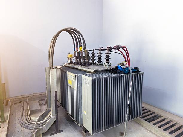
Where a delta-connected network requires a neutral reference, a grounding transformer can provide an artificial neutral point. Common configurations include zigzag transformers and appropriately designed wye-delta arrangements.
These transformers provide a path for zero-sequence current associated with earth faults, allowing the system to be grounded directly or through an impedance selected for the application. The grounding transformer must be designed for the intended network voltage and fault-duty requirements. <Cite refs={[“turn836175search0″,”turn836175search1″,”turn836175search6”]}/>
Ground-fault current is one of the most important factors in grounding transformer selection. The design must establish how much current can flow during a fault, how long the equipment must withstand it, and how the protection system will detect and clear the condition.
For resistance-grounded systems, a neutral grounding resistor can limit earth-fault current to a predetermined level. The grounding transformer, resistor, conductors, and protective devices must all be rated for the expected electrical and thermal stresses.
Engineers should evaluate the following parameters:
A grounding transformer may have a relatively modest continuous load rating while requiring substantial short-time fault-current capability. Its specification must reflect both operating conditions and the anticipated fault duty.
The calculations should be based on the actual network characteristics, not solely on the connected load’s total kilovolt-ampere rating.
A grounding arrangement is only effective when the protection system can detect relevant faults and initiate the appropriate response.
Ground-fault relays, current transformers, residual-current sensing arrangements, and other monitoring devices may be used depending on the network configuration. Their selection and settings must reflect the expected fault-current magnitude and the sensitivity required for the installation.
For example, a resistance-grounded industrial network may produce a deliberately limited earth-fault current. Conventional overcurrent protection may not provide adequate sensitivity under every condition, so dedicated ground-fault protection may be necessary.
Protection coordination should consider both the grounding equipment and downstream circuits. Engineers should verify that protective devices operate selectively where required, limiting the extent of an outage while ensuring faults are cleared within safe time limits.
The design should also account for changes in network configuration, including transformer switching, generator operation, and the addition of new distribution sections.
Correct installation is essential to achieving the intended grounding performance. Grounding conductors, bonding connections, transformer enclosures, and associated equipment must be installed according to the approved design and applicable electrical requirements.
Engineers should verify that:
A grounding transformer does not replace protective earthing of equipment. System grounding and equipment bonding perform related but distinct functions, and both must be considered in the overall electrical safety design.
Particular care is required when modifying an existing delta system. An unintended connection between a floating conductor, neutral point, or earth can alter the system’s electrical behaviour and potentially compromise protection.
Grounding requirements vary with the installation’s location, voltage level, application, and governing electrical regulations. Engineers should identify the standards and statutory requirements that apply before finalising a design.
IEEE guidance on industrial power system grounding provides a technical framework for assessing grounding methods, ground-fault behaviour, and equipment requirements. The IEEE C62.92 series also addresses neutral grounding considerations for electrical utility systems, including distribution networks. <Cite refs={[“turn836175search14″,”turn836175search5″,”turn836175search16”]}/>
In India, project teams should additionally consider the applicable Central Electricity Authority regulations, relevant Bureau of Indian Standards publications, utility requirements, and project specifications, as appropriate.
Compliance review should cover the complete installation rather than the transformer alone. A technically suitable grounding transformer does not automatically make the overall network compliant if protection settings, conductor sizing, bonding, or installation practices are inadequate.
Grounding systems require periodic inspection to confirm that their components remain functional and that the installed arrangement continues to match the approved design.
Maintenance activities should be selected according to the equipment manufacturer’s instructions, the facility’s risk assessment, and applicable regulations. Depending on the installation, inspections may include checking connections for deterioration, examining grounding resistors for signs of overheating, and verifying the condition of protective relays and monitoring equipment.
Electrical testing may also be needed following major modifications, protection-system changes, or suspected equipment damage.
All inspection and testing should be carried out by qualified personnel using appropriate procedures and instruments. Before work begins, the equipment must be isolated and verified safe under the site’s approved electrical safety procedures.
Industrial facilities frequently add production machinery, variable-frequency drives, generators, and new distribution panels as operations grow. These changes can affect cable capacitance, available fault current, protection coordination, and the performance of an existing grounding arrangement.
A grounding design that was suitable for the original installation may therefore require reassessment after expansion.
Meta Power Solutions encourages a design-led approach to electrical infrastructure planning, where grounding requirements are reviewed alongside transformer capacity, distribution architecture, and future operational needs. A documented review helps identify potential compatibility issues before they affect reliability or require costly corrective work.
Evaluating grounding delta transformer requirements is an important part of designing and maintaining safe, reliable industrial electrical networks. The process begins with understanding the existing transformer configuration and selecting a grounding method that suits the system’s operating conditions. Engineers must then assess ground-fault current, transformer duty, protective relay coordination, equipment bonding, and applicable regulatory requirements.
Ungrounded delta, corner-grounded delta, and grounding transformer arrangements each serve different purposes. No single method is appropriate for every industrial installation, and the final decision should be based on documented engineering calculations and a complete review of the electrical network.
Regular maintenance and reassessment following system modifications help preserve grounding performance throughout the installation’s service life. By prioritising sound engineering, protection coordination, and regulatory compliance, Meta Power Solutions highlights the importance of grounding decisions that support electrical safety, operational reliability, and long-term infrastructure planning.
The ultimate objective is not simply to establish a connection to earth, but to ensure that the complete electrical system responds predictably and safely when abnormal conditions occur.